Ask ten installers whether an air-to-water heat pump needs a buffer tank and you will get ten different answers. Some fit a 100 litre vessel on every job by reflex. Others argue that a modern inverter machine makes buffers obsolete. Both camps are partly right.
A buffer tank is not a default component. It fixes three specific problems: not enough water volume in the circuit, not enough flow through the heat pump, and hydraulic separation between the heat pump loop and a zoned emitter system. If your installation has none of those problems, a buffer adds cost, standing losses and stratification headaches for no benefit. If it has any one of them, leaving the buffer out shows up as short cycling, nuisance defrost behaviour and a seasonal efficiency figure well below the datasheet.
· A buffer tank solves three distinct problems: low system water volume, insufficient minimum flow rate, and hydraulic separation for zoned or mixed emitter systems.
· Fixed speed and narrow modulation heat pumps almost always need one, because the machine cannot turn down to match a small heat demand.
· A wide range inverter heat pump paired with a high volume emitter system (screed underfloor heating, generous radiators, open circuits with no thermostatic restriction) can often run with no buffer at all.
· A rough starting point for volume sizing is 10 to 20 litres per kW of heat pump output, then check it against the manufacturer's stated minimum system volume and defrost energy requirement.
· A buffer in the return (a volumiser in series) preserves flow temperature and efficiency far better than a poorly configured 4-pipe buffer, which can force the heat pump to run hotter than the emitters need.
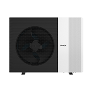
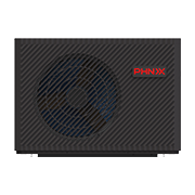
· PHNIX GreenTherm Pro is an R290 air-to-water heat pump with AI Full Inverter control, tested by TUV SUD RED and HLK Stuttgart at SCOP 5.55, and its wide modulation range is what allows many installations to reduce or eliminate buffer volume.
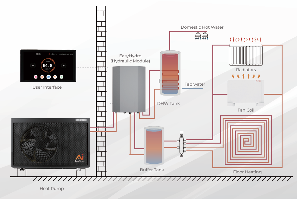
A buffer tank is a vessel of system water sitting between the heat pump and the emitters. It is not a domestic hot water cylinder, it holds heating water only, and it is usually unpressurised in relation to potable supply. Its job is thermal inertia.
Every compressor has a minimum output. When heat demand falls below that minimum, the heat pump either turns off and restarts later (cycling) or dumps heat into something that can absorb it. A buffer tank is the something. It gives the machine a slug of water large enough to accept a full minimum-output run of ten minutes or more, so the compressor is not stopping and starting every three minutes on a mild April afternoon.
Cycling is not just an annoyance. Each start draws inrush current, each stop leaves refrigerant migrating, and the compressor spends a disproportionate share of its runtime in the least efficient part of its curve. Field data across the sector consistently shows heavily cycling installations losing a meaningful share of seasonal performance against the same hardware running long, steady, low temperature cycles.
The second job is flow. Air-to-water heat pumps specify a minimum flow rate to keep the plate heat exchanger out of trouble and to guarantee enough energy is available for reverse cycle defrost. If a room thermostat closes the last zone valve, flow can collapse. A buffer keeps a guaranteed path open.
The third job is hydraulic separation. With mixed emitters, underfloor circuits at 35 C and a towel rail loop at 45 C, or long high resistance pipe runs, a buffer with its own secondary pump decouples the heat pump's flow requirement from the emitter circuit's variable flow.
Skipping the buffer is a legitimate design choice, not a shortcut, provided you can demonstrate all of the following.
· The system water volume already meets the manufacturer's stated minimum. A screed underfloor system in a whole house typically holds several hundred litres, often more than any buffer you would fit.
· The heat pump can modulate below the building's mildest weather heat loss. This is where a wide range inverter matters most.
· No control strategy can close off flow. That means weather compensation with emitters left open, no zone valves slamming shut, and no thermostatic radiator valves throttling the last open circuit.
· Defrost energy can be drawn from the circuit without the flow temperature crashing below the low limit.
If any one of those four fails, fit the buffer. The most common failure in retrofit work is the third: a legacy system full of thermostatic radiator valves, where the installer keeps the existing controls and then wonders why the heat pump alarms out.
Not all buffers are equal, and the piping arrangement matters more than the litres.
| Configuration | Adds volume | Provides hydraulic separation | Risk of raising flow temperature | Typical use |
|---|---|---|---|---|
| Volumiser in return (2-pipe, in series) | Yes | No | Lower | Inverter unit, single zone, just needs volume |
| 4-pipe buffer with secondary pump | Yes | Yes | Higher | Multi-zone, mixed emitters, long pipe runs |
| Low loss header | No | Yes | Moderate | Flow decoupling only, no inertia gained |
| Open manifold with no vessel | No | Not applicable | Lower | High volume underfloor, wide range inverter |
The pattern is clear. If you only need volume, use a volumiser in the return line and keep the hydraulics simple. Reach for the 4-pipe buffer only when you genuinely need separation, and accept that you will usually run the heat pump a few kelvin hotter to deliver the same emitter temperature.
Start with three numbers and take the largest result.
· Manufacturer minimum system volume. Subtract the volume already in pipes, emitters and manifolds. The remainder is what the buffer must supply. This alone settles many jobs.
· Minimum run time. Take the compressor's minimum output in kW, decide the shortest acceptable run (commonly 10 minutes), and allow a working swing of around 5 K. Volume in litres is roughly minimum output in kW multiplied by 172, multiplied by run time in hours, divided by the swing in K.
· Defrost reserve. Reverse cycle defrost pulls energy back out of the circuit in a short burst, and flow temperature must not fall below the unit's cutoff.
As a sanity check, 10 to 20 litres per kW of rated output covers most residential jobs. A 10 kW machine on a mixed radiator system typically lands between 100 and 200 litres. Going far larger is a false economy: the standing loss is permanent, stratification worsens, and the system responds more slowly to weather changes.
Design heat load should come from a room by room calculation to EN 12831. Steady state rated COP is measured to EN 14511, while seasonal performance (SCOP) comes from part load testing to EN 14825, the basis for the ErP seasonal space heating efficiency figure. A machine chosen on rated COP alone is easily oversized, and then needs a large buffer to hide the mismatch.
The buffer tank convention came from an era of fixed speed compressors that were either at full output or off. On a 12 kW fixed speed unit serving a house with a 3 kW mild weather load, the machine has no choice but to cycle unless a large mass of water absorbs the surplus. Variable speed compressors changed that arithmetic. A wide range inverter can hold a low output for hours, matching mild weather demand directly and eliminating most cycling without any stored volume at all.
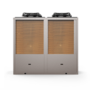
PHNIX GreenTherm Pro is an R290 air-to-water heat pump rated A+++ for low temperature application (seasonal space heating efficiency of at least 175 percent under Regulation (EU) 811/2013 Annex II Table 2), with EVI low temperature technology for stable operation down to minus 30 C and PV integration. Its AI Full Inverter control, trained on operating data from more than 30,000 units in the field, delivers over 30 percent energy savings against conventional inverter control in residential applications by holding low, steady output rather than cycling. That control behaviour is precisely what allows many installations to use a modest volumiser instead of a full 4-pipe buffer. You can see the range in the residential heating and cooling heat pump line-up, and the independently verified performance data is published on the TUV SUD RED and HLK Stuttgart SCOP 5.55 test page.
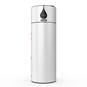
For apartments and older properties where an outdoor unit and a buffer simply will not fit, the airMono R290 indoor monobloc removes the outdoor unit from the equation, which changes the space budget for hydronic components entirely. Full technical detail sits on the GreenTherm Pro R290 product page.
Buffer decisions do not sit in isolation from refrigerant choice, because the machines still legally available in a few years will overwhelmingly be low GWP units.
Under Regulation (EU) 2024/573, which has applied since 11 March 2024 and repealed Regulation 517/2014, R290 has a GWP100 of 0.02 (Annex VI) while R32 has a GWP100 of 675 (Annex I) and remains inside the HFC quota system. Annex IV restricts monobloc and self-contained heat pumps up to 12 kW containing refrigerants with GWP of 150 or more from 1 January 2027, with the same date for split air-to-water units up to 12 kW. R410A and R454B are blends and are not listed individually in the annexes of Regulation (EU) 2024/573, but both sit far above the 150 GWP threshold that drives the 2027 restrictions. Article 13(4) separately bans fluorinated gases with GWP of 2500 or more from servicing air conditioning and heat pump equipment from 1 January 2026.
For propane systems, charge limits are set by refrigerant LFL and room or installation volume under EN 378 and IEC 60335-2-40 (7th edition, 2022); confirm the actual clearance with local installation rules and the manufacturer's manual. A buffer tank in a plant room does not change the refrigerant safety envelope, since the refrigerant circuit stays sealed inside the heat pump.
PHNIX holds CE, UKCA, Keymark, AHRI, ETL and ERP certifications, with AHRI performance audits passed at 100 percent compliance for three consecutive years (2023, 2024 and 2025).
A buffer is not free efficiency. Three costs are worth quantifying with the customer.
· Standing loss. Even a well insulated 200 litre vessel loses heat continuously to the plant room, which over a heating season is real kilowatt hours.
· Flow temperature penalty. A 4-pipe buffer with mixing typically forces the heat pump to run 2 to 5 K hotter than the emitters need. As a rule of thumb across the sector, each kelvin of extra flow temperature costs roughly 2 to 2.5 percent of COP.
· Space and cost. Plant room area, pipework, an extra pump and its parasitic electricity consumption.
Put numbers on it. Using the Eurostat household electricity price for the second half of 2025, taxes included, in the 2,500 to 5,000 kWh band, the EU27 average is 0.2896 EUR per kWh. A system consuming 4,000 kWh a year that loses 5 percent of its efficiency to an unnecessary buffer arrangement is spending roughly 58 EUR a year for nothing.
Grant and tax context shifts the calculation too. In the United Kingdom, the Boiler Upgrade Scheme pays 7,500 GBP for an air source heat pump, and energy saving materials carry a zero VAT rate from 1 May 2023 until 31 March 2027, reverting to 5 percent from 1 April 2027. In Ireland, heat pump installation is charged at 9 percent VAT under VATCA 2010 s.46(1)(ca). In France, a rénovation d'ampleur project attracts support at 80, 60, 45 or 10 percent of eligible cost by income band, with 5.5 percent TVA. Those schemes fund the heat pump and its hydronics together, so the buffer usually sits inside the funded scope.
Q: Can I use my domestic hot water cylinder as a buffer tank?
A: No. A domestic hot water cylinder stores potable water at a different temperature regime and is charged by a dedicated diverter cycle, while a buffer holds heating circuit water. Combining them is only valid with a purpose designed thermal store that has separate, correctly sized coils, and even then space heating stratification usually suffers.
Q: If I fit a bigger buffer, will my heat pump be more efficient?
A: Not beyond the point where cycling has stopped. Once the vessel guarantees acceptable run times and defrost energy, extra volume only adds standing loss and slows response to weather compensation. Size it to the calculated need, then stop.
Q: Does a buffer tank help with defrost?
A: Yes, and it is often the deciding factor in cold climates. With too little volume, flow temperature drops below the low limit during defrost and the unit trips or delivers a cold blast to the emitters. Confirm the required defrost energy reserve in the manufacturer's manual rather than assuming.
A buffer tank is a targeted remedy, not a default fitting. Check three things in order: does the circuit already hold the manufacturer's minimum system volume, can the compressor modulate below mild weather demand, and can any control action starve the unit of flow. If all three answers are favourable, fit no buffer and enjoy the lower flow temperature and the reclaimed cupboard. If any answer is unfavourable, size the smallest vessel that fixes the specific problem, prefer a volumiser in the return over a 4-pipe buffer wherever separation is not genuinely required, and verify by logging compressor run times through a real heating season.
Wide range inverter control moved this boundary. PHNIX, founded in 2002 with more than 1,000 employees, exports to over 90 countries and has filed 1,816 patents while contributing to more than 70 national and industry standards, and its AI Full Inverter platform is built around the long, low, steady operation that makes large buffers unnecessary in most residential retrofits. Explore the portfolio at the PHNIX website or speak to the technical team before finalising your hydronic design.

Guangdong PHNIX Eco-energy Solution Ltd.
Tel: +86-4009-4009-00
Address: NO.3 Tianyuan Road, Dagang Town,
Nansha, Guangzhou, Guangdong, PR. China.